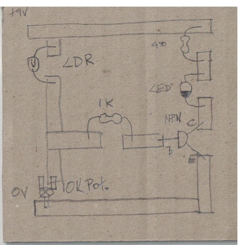
Transistor as a Switch CIRCUIT
TASK
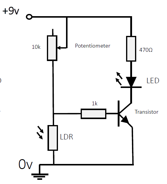
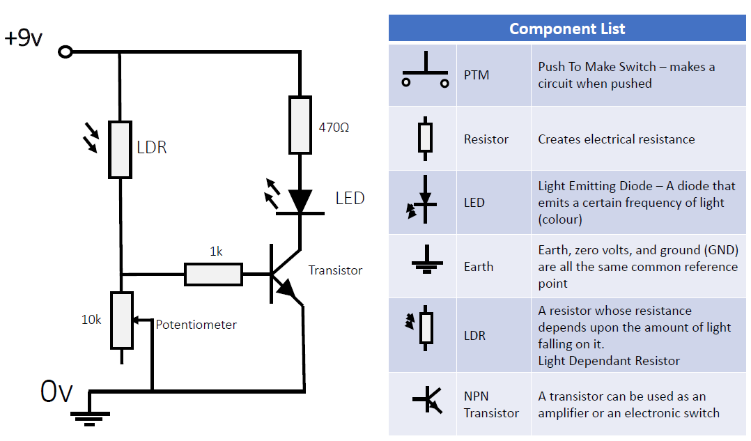
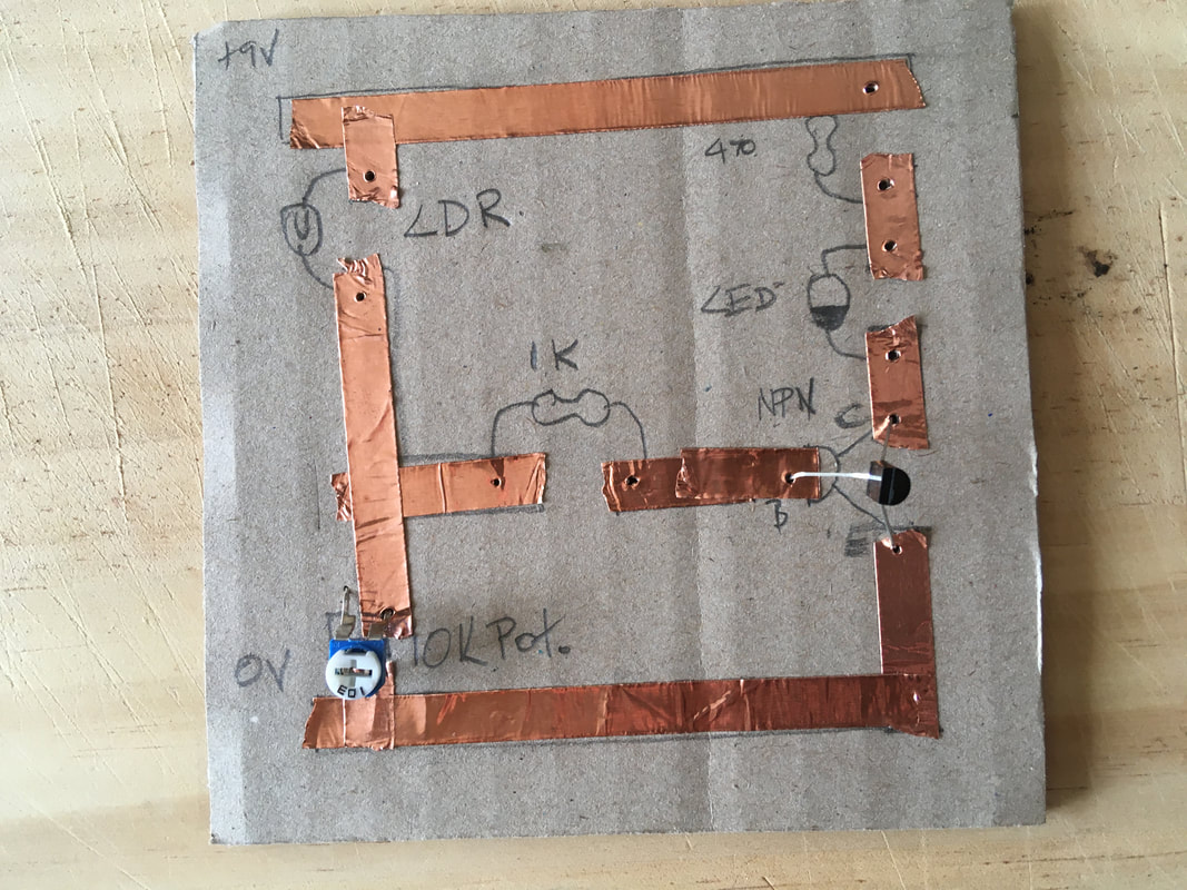
Look at the diagram above:
1. What components do you recognise?
2. What components are new?
3. Write the new components LDR and NPN Transistor into your Terminology and Meaning list.
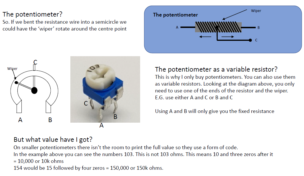
Also include "Potentiometer: A resistor that can change it's resistance".
4. Write the heading amd draw and label the diagram.
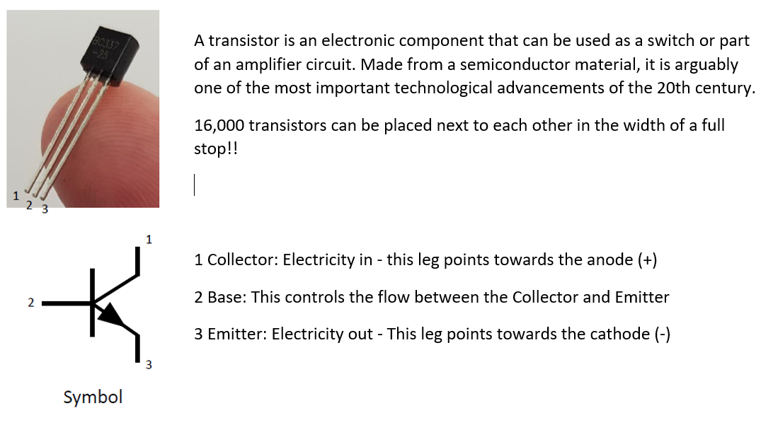
WHAT IS A TRANSISTOR?
CHECK: DO ALL LEARNERS HAVE THEIR CONTAINER? THEY NEED A TRANSISTOR, POTENTIOMETER, 1K RESISTOR, AND A LIGHT DEPENDENT RESISTOR
TASK
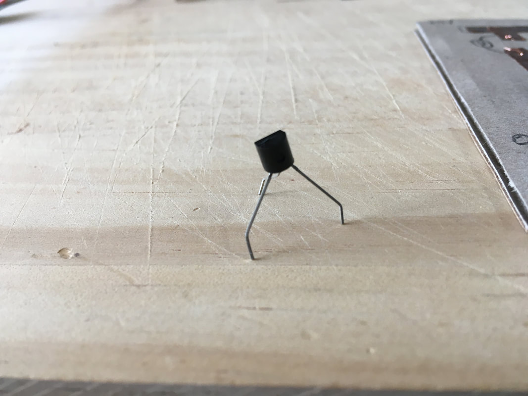
Pick up your transistor:
Identify the Collector, Base and Emitter. Make sure you are looking at the flat side.
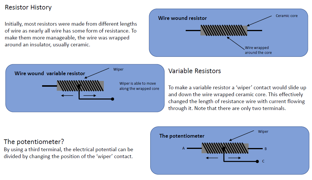
HISTORY OF RESISTORS AND THE POTENTIOMETER
TASK
Pick up your potentiometer:
Identify the A, B and C.
Check it's value.
Can you see how it works.
|
|
CIRCUIT CONSTRUCTION
WARNING: WILL BE USING A HOT SOLDERING IRON. POTENTIAL HAZARD
Materials needed:
1 x plastic container for components
1 x a piece of cardboard approximately 100 x 100 mm
1 x length of copper tape
1 x resistor 470 ohms
1 x resistor 1K ohms
1 x potentiometer 10K ohms
1 x LEDs (Light Emitting Diodes)
1 x 9v battery clip
1 x NPN transistor
1 x Light Dependent Resistor
SHORT CIRCUIT
Now that there are quite a few components on our circuit board there may be quite a number of wires on the other side. These wires must NOT TOUCH. Why? Because they will cause a short circuit, these means the electricity will flow in way that we didn't intend. This will usually cause the circuit not to operate as intended.
USING PLIERS AND OTHER TOOLS
No tools can be removed from the room. All tools cost money which is not easy to come by. If any tools are removed that puts the viability of this course at risk.
ATTACHING TRANSISTOR AND POTENTIOMETER
You need to be gentle and careful with the components. Take your time attaching them to the board. Pliers can be used to bend the wire ends.
USE PLIERS TO BEND WIRE IF NEEDED
|
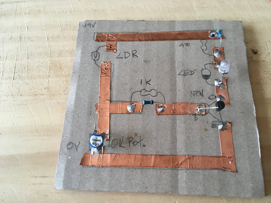
ATTACH COMPONENTS CAREFULLY SO AS NOT TO CAUSE A SHORT CIRCUIT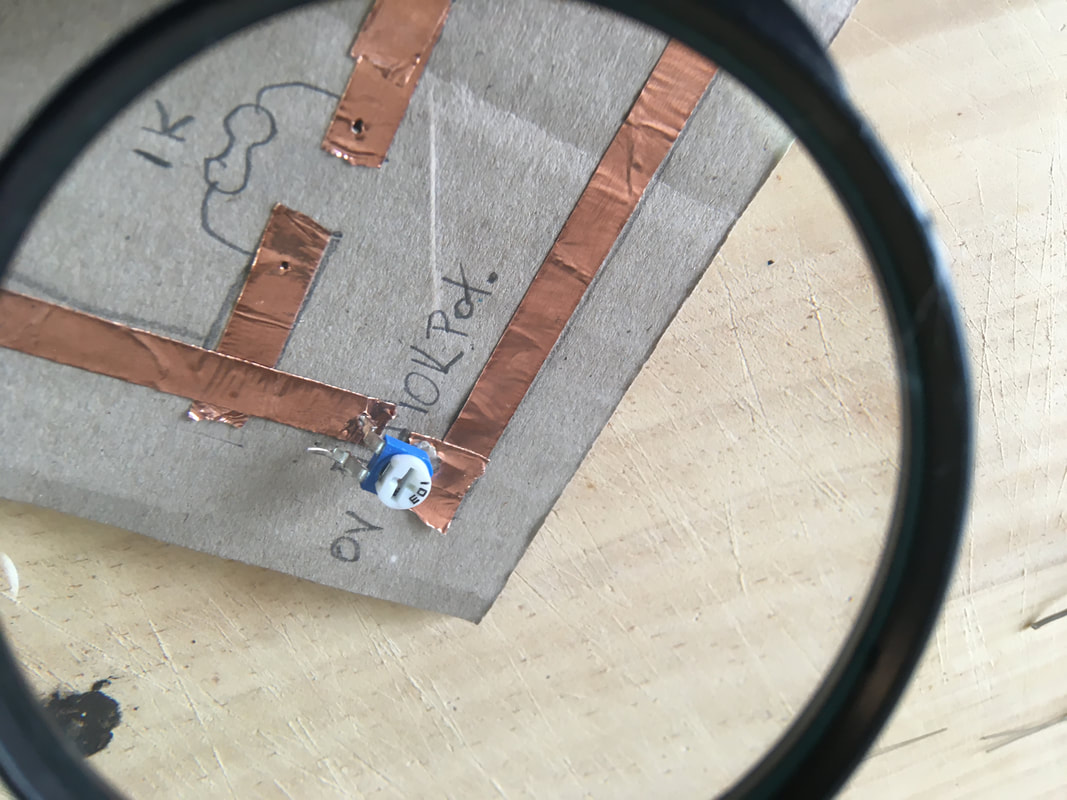
|
|
|
|
|
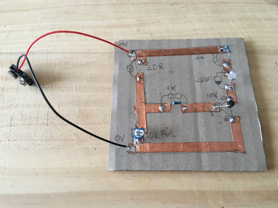
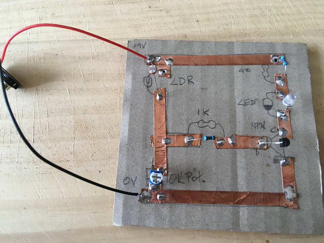
ADD THE BATTERY AND TEST THE CIRCUIT
Initially, the circuit will not work. This is because the circuit needs to be ‘tuned in’.
For the LED to turn on and off the voltage level at the transistor collector needs to be ‘just right’ (0.7v).
The easiest way to do this is to turn the potentiometer all the way back and forth until you find the place where a small movement turns the LED on and off.
Make the LED only just turn on.
Really only just!
Shade the LDR and the LED should turn off.
Electronic magic!
|
|
WATCH THE VIDEO
|
What Uses Could This Circuit Be Put To?
This circuit has a variety of uses if we think about it. One might be a light dependant device of some sort. One that turns on when it get dark. This can be achieved by swapping the LDR and potentiometer positions.
CHALLENGE
Try swapping these two components on the circuit to see what happens.