Parallel CIRCUIT
CHECK: DO ALL LEARNERS HAVE THEIR CONTAINER AND RESISTOR/ LED CIRCUIT? WILL ALSO NEED SOLDERING IRON, PLIERS, AND IRON HOLDERS.
Recycle your components used in the 'Resistor/ LED Circuit
To keep costs down and to save energy by recycling we will be breaking up our first circuit and reusing the components. This shouldn't take too long. The solder you applied will melt quickly to free the component. Be careful that you don't heat the LED too much (10sec with a 20 watt iron is the maximum). If you are using a 40W iron then 2-3 seconds at a time maximum.
TASK
You need to recycle 3 components
-1- The 9v battery clip
-2- The 470 Ohm resistor
-3- The LED
When the components are cool put them into your container. If the the card is reusable then we will reuse it as well.
CIRCUIT CONSTRUCTION
WARNING: WILL BE USING A HOT SOLDERING IRON. POTENTIAL HAZARD
Materials needed:
1 x plastic container for components
1 x a piece of cardboard approximately 100 x 100 mm
1 x length of copper tape
1 x resistor 470 ohms
3 x LEDs (Light Emitting Diodes)
1 x 9v battery clip
METHOD
1. Check you have the correct materials
2. Watch the demonstration (to refresh your knowledge) of how to use a solder iron. Here's a useful video https://youtu.be/Qps9woUGkvI
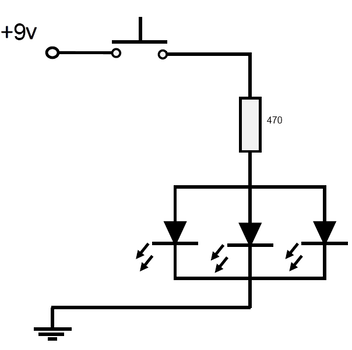
3. Draw up the circuit diagram on the card (its shown below)
4. Stick on copper tape (take your time- there is limited copper tape)
5. Make your PTM switch, add it to your circuit
6. Solder on the resistor (Can face either direction)
7. Solder on LEDs (Careful with the polarity, and heat used. 2-3 seconds if using a 40W iron, 10sec if using a 20W iron)
8. Solder connections in the copper tape
9. Use a multimeter continuity test the connections in your circuit. Swap with another learner to check theirs. If there are problems with continuity your circuit won't work. Recheck method.
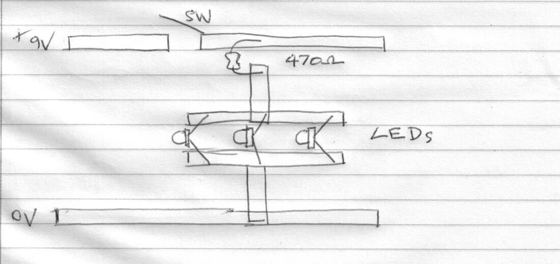
Parallel Circuit layout |
|

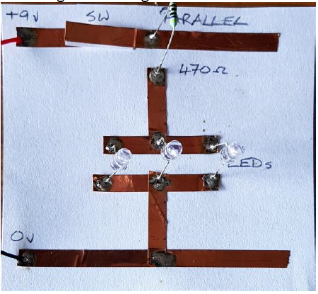
IMAGES THAT MAY HELP BUILDING THE CIRCUIT
Here are some images of the circuit being built.
EXERCISE BOOK - WRITE UP RESULTS ON CONTINUITY TESTING
Write a heading for the "Parallel Circuit". Draw the circuit diagram (see below).
Write a heading "ContinuityTesting"
Write "Method" and describe the construction of the circuit from the beginning. Make sure you include the continuity tests you did.
Terminology and meanings
Update the list at the back of your exercise book.
Parallel circuit: A parallel circuit is a closed circuit in which the current divides into two or more paths before recombining to complete the circuit. Each load connected in a separate path receives the full circuit voltage, and the total circuit current is equal to the sum of the individual branch currents
TASK
Add Parallel Circuit to your Terminology and Meanings in your exercise book.
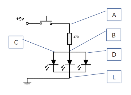
LEDs IN PARALLEL
MEASURING VOLTAGE IN A PARALLEL CIRCUIT
|
|
USES FOR THIS PARALLEL CIRCUIT
This circuit is very useful as the LED's have equal voltage. It could be used to provide light to LED's in a project where light would be useful. The eyes of an animal, or a constellation in the sky. There are many applications.
HOW TO CHOOSE THE RESISTOR
First it's necessary to know a bit about Ohms Law. This video is a good introduction.
This website gives a brief and to the point explanation: https://www.kitronik.co.uk/blog/which-resistor-should-i-use-with-my-led/
Ohms Law
It is necessary to use Ohms Law for electricity. Ohms Law describes the relationship of current, resistance and voltage in an electrical circuit.
Its says:
V=IxR or Voltage = Current x Resistance
Current (I) is the flow of the electricity in the circuit. It is measured in Amps.
The forward voltage for an LED is typically 0.7 volts (This is the minimum voltage for the LED to function).
The current allowable for an LED is typically 0.02 amps (or 20 milliAmps).
It is necessary to have a resistor of a minimum of 290 Ohms. Too much current will destroy the LED.
TASK
Add Current and Ohms Law to your Terminology and Meanings in your exercise book.
Current: The flow of electricity in a circuit.
Ohms Law: V = I x R describes the relationship of voltage, current and resistance in an electrical circuit
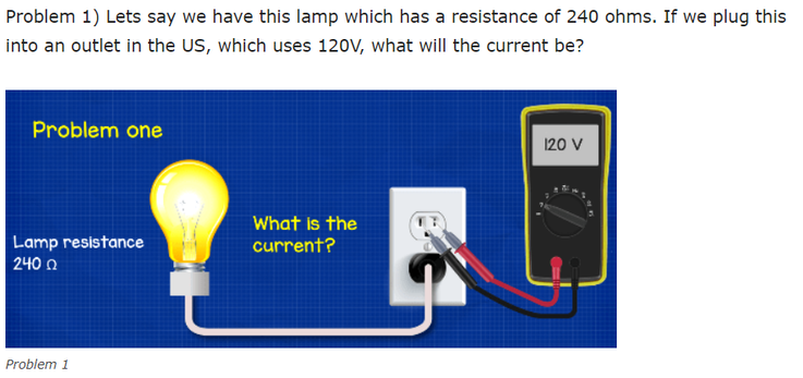
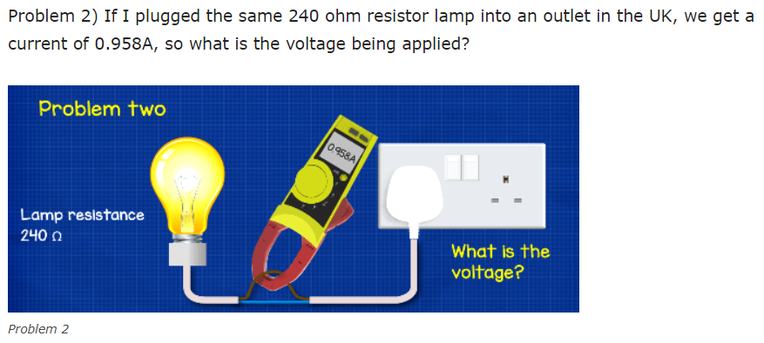
OHMS LAW - TEST YOUR SKILLS
Can you solve these two problems?