Series CIRCUIT
CHECK: DO ALL LEARNERS HAVE THEIR CONTAINER AND RESISTOR/ LED CIRCUIT? WILL ALSO NEED SOLDERING IRON, PLIERS, AND IRON HOLDERS.
Recycle your components used in the 'Parallel Circuit
To keep costs down and to save energy by recycling we will be breaking up our parallel circuit and reusing the components. This shouldn't take too long. The solder you applied will melt quickly to free the component. Be careful that you don't heat the LED too much (10sec with a 20 watt iron is the maximum). If you are using a 40W iron then 2-3 seconds at a time maximum.
TASK
You need to recycle 3 components
-1- The 9v battery clip
-2- The 470 Ohm resistor
-3- The LEDs (x3)
When the components are cool put them into your container. If the the card is reusable then we will reuse it as well.
CIRCUIT CONSTRUCTION
WARNING: WILL BE USING A HOT SOLDERING IRON. POTENTIAL HAZARD
Materials needed:
1 x plastic container for components
1 x a piece of cardboard approximately 100 x 100 mm
1 x length of copper tape
1 x resistor 470 ohms
3 x LEDs (Light Emitting Diodes)
1 x 9v battery clip
METHOD
1. Check you have the correct materials
2. Watch the demonstration (to refresh your knowledge) of how to use a solder iron. Here's a useful video https://youtu.be/Qps9woUGkvI
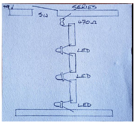
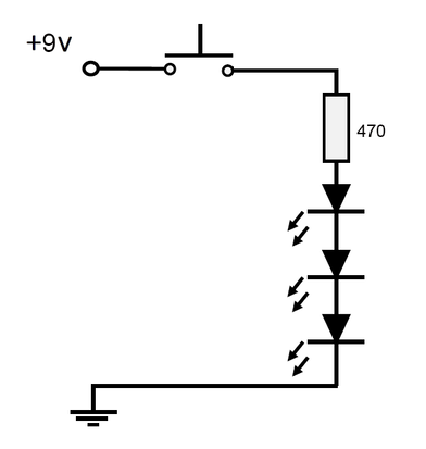
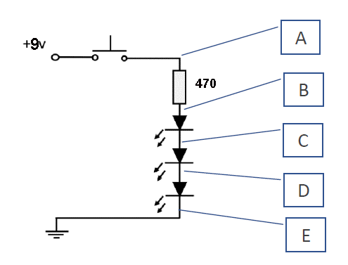
3. Draw up the circuit diagram on the card (its shown below)
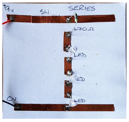
4. Stick on copper tape (take your time- there is limited copper tape)
5. Make your PTM switch, add it to your circuit
6. Solder on the resistor (Can face either direction)
7. Solder on LEDs (Careful with the polarity, and heat used. 2-3 seconds if using a 40W iron, 10sec if using a 20W iron)
8. Solder connections in the copper tape
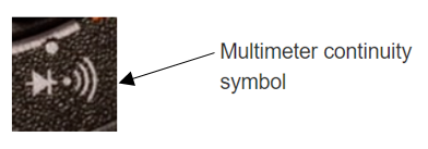
9. Use a multimeter continuity test the connections in your circuit. Swap with another learner to check theirs. If there are problems with continuity your circuit won't work. Recheck method.
|
|
EXERCISE BOOK - WRITE UP RESULTS ON CONTINUITY TESTING
Write a heading for the "Series Circuit". Draw the circuit diagram (see below).
Write a heading "ContinuityTesting"
Write "Method" and describe the construction of the circuit from the beginning. Make sure you include the continuity tests you did.
Terminology and meanings
Update the list at the back of your exercise book.
Series circuit: A series circuit has only one path in which its current can flow.
TASK
Add Series Circuit to your Terminology and Meanings in your exercise book.
LEDs IN SERIES
MEASURING VOLTAGE IN A SERIES CIRCUIT
|
|
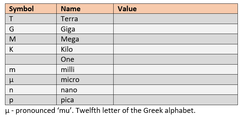
UNITS OF MEASUREMENT
Some values for electrical measurements can be small and others large. Current is often a small value and Resistance a large value. To show the value of electrical measurement these units of measurement are common.